Senior-level Ansys FEA and CFD for aerospace, automotive, and industrial teams. Nonlinear physics, certification-grade documentation, fixed-fee engagements. The person presenting the proposal is the person building the model.
We don't sell "capability" — we sell the specific analyses that fail in your existing team or your existing consultant. Nonlinear contact on glass-fiber parts. Transient CHT coupled to LCF. PSD vibration with Dirlik damage. The problems where default settings produce a plausible-looking stress plot that's wrong by 50%.
Senior-level finite element analysis for problems most teams avoid — geometric and material nonlinearity, contact mechanics, fatigue life prediction, vibration. Results your team can defend in front of a reviewer.
Dedicated CFD for fluid systems — for the pressure drops, heat transfer rates, and thermal cycles too critical to approximate and too complex for hand calculations. Boundary conditions that are justified, not guessed.
Pick the scenario closest to yours — we'll show the physics, the methodology, the deliverable, and a realistic timeline.
Every industry has its own documentation vocabulary and its own definition of "good enough". We work to the standard the regulator, the customer, or the insurer will actually accept.
Coupled transient CHT + thermo-mechanical LCF. DER-acceptable documentation. CMSX-4, IN718, Ti-64 with calibrated material cards.
Nonlinear polymer & rubber FEA with Moldflow → Ansys fiber mapping. PSD vibration with Dirlik fatigue. The weld-line problem nobody catches.
ASME VIII Div.2 / EN 13445 DBA. API 579 fitness-for-service. IIW weld fatigue. Reports written for the AHJ, not the shelf.
Scoped upfront, reviewed at each gate. The purpose of the process is to eliminate surprise at the end — not generate billable hours in the middle.
30 minutes. Component, loading, question. We'll tell you what type of analysis is appropriate.
Within 48 hours. Analysis plan, assumptions, boundary conditions, deliverable, and price.
CAD simplification, mesh, material cards, BCs. One review gate before solve.
Three-level mesh study. Sensitivity on critical BCs. Engineering quantity tracked to stability.
Structured for DER, AHJ, or internal DR. Model files + raw data. Debrief call included.
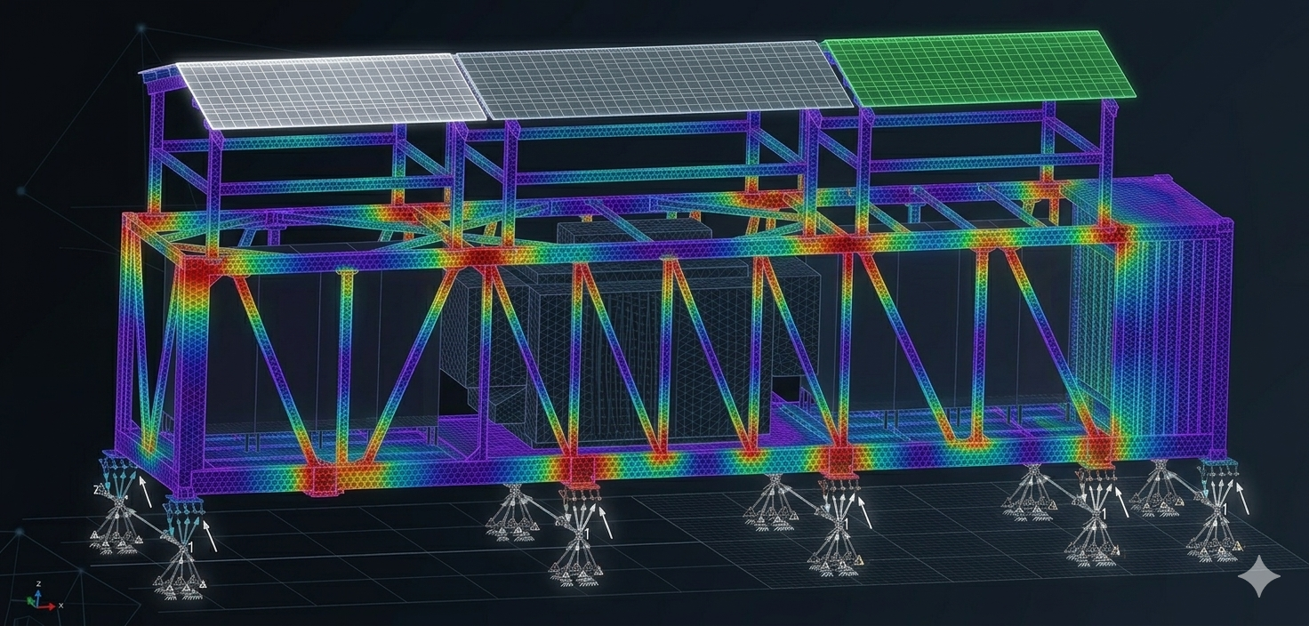
49+ load sub-cases across wind, snow, ice, and seismic combinations — all per ASCE 7-22. Governing case: seismic at 225.8 MPa / 96% utilization. All columns in net compression — no hold-down anchors required. Per-column reaction tables delivered directly to foundation engineers.
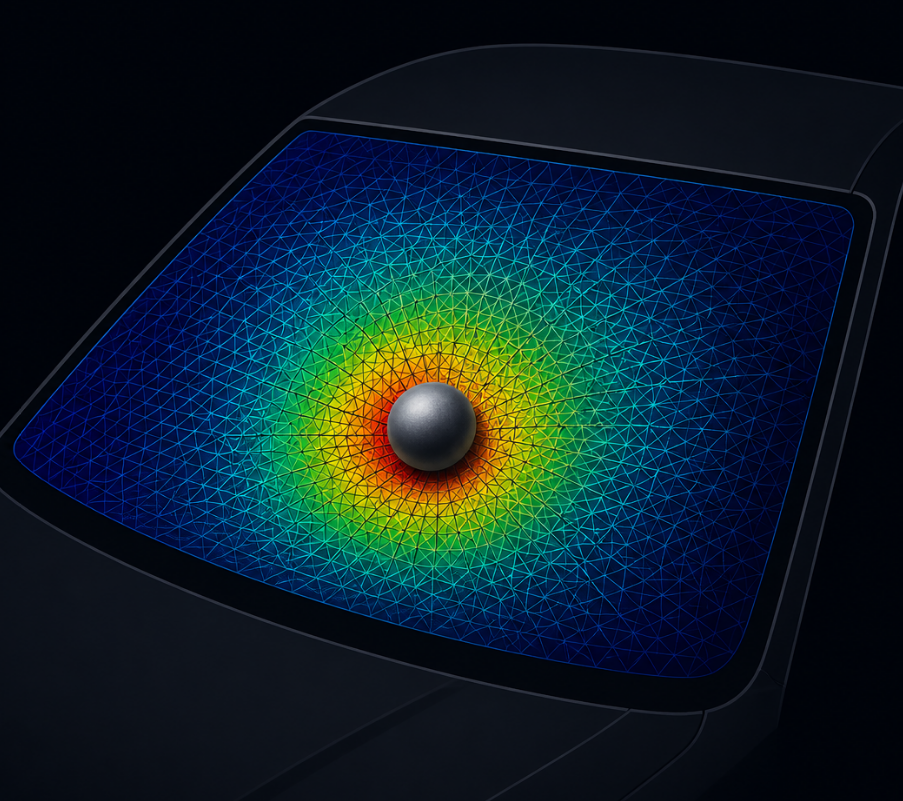
JH-2 + XFEM + Prony PVB + CZM in a single explicit model. HIC(d) = 834 under ECE R43 limit. PVB optimum identified at 0.76 mm — 22% compliance margin, +18% mass.
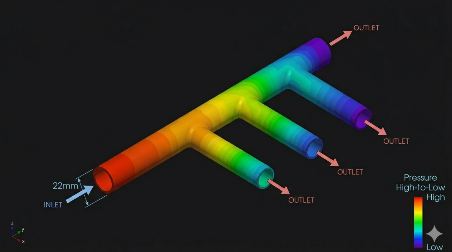
k-ω SST steady-state CFD on 7.8M cells pinpointed T-junction (31%) and bends (28%) as dominant losses. Four geometry changes cut ΔP from 18.6 to 13.1 kPa — pump power from 132 W to 93 W.
VFM + DIC identifies all 5 JC parameters simultaneously from heterogeneous strain fields. Independent impact validation: 4.2% peak force error vs 11% for classical methods.
A 12-second startup transient drove peak stress at a cooling-channel fillet nobody had flagged. One geometry change moved predicted life from 8,200 to 24,000 cycles.
Isotropic analysis predicted 2× margin. Process-aware fiber orientation showed 58% strength drop at the weld line — exactly where the prototype cracked.
Branch-1 was taking 2.6× design flow. CFD identified the header geometry that equalized distribution within 8% — before a single part was machined.
Large consultancies sell the engagement with a senior, then rotate a junior analyst onto your project. You find out at the design review when the results don't make sense — six weeks of program time burned.
Simforge is the opposite. The person who scopes the project builds the model, solves it, writes the report, and stands behind the result. Eight years inside Tier-1 automotive CAE means we read OEM specifications in the original language — no two-week onboarding required.
Price and deliverable locked before work starts. No utilization-driven scope creep.
Typical structural or CFD study is three weeks from geometry to signed report.
Reports structured for your DER, AHJ, or internal DR — not a working file.
Confidentiality is the default. Formal NDAs immediately available as standard.
30 minutes. The component, the loading, the question. We'll tell you whether it's a three-week problem or a three-month one — and whether simulation is even the right tool.